
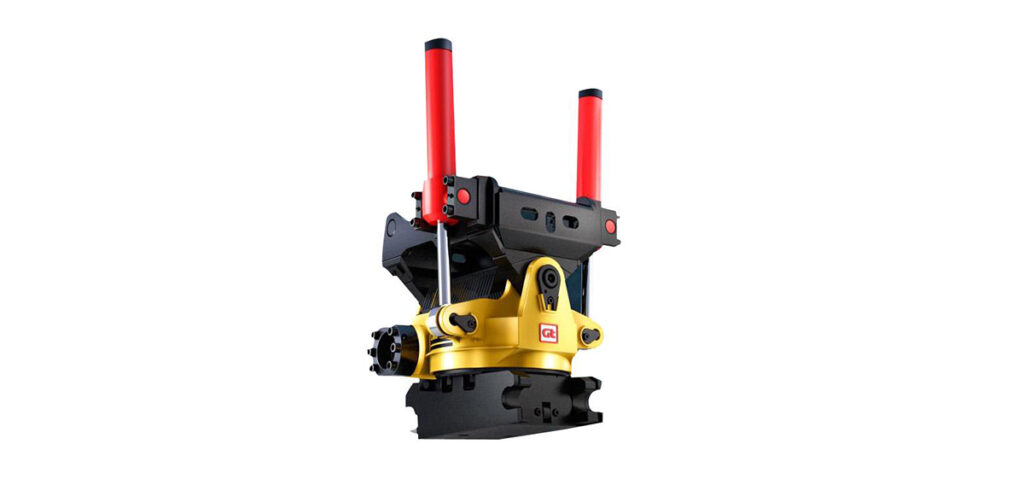
SWINGING CYLINDER TYPE TILTROTATOR
| SWINGING CYLINDER TYPE TILTROTATOR | ||||||
| Model | GRT-40 | GRT-50 | GTR-60 | GTR-70 | GTR-80 | |
| Applicable Excavator(T) | 3.0-7.0 | 7.0-12.0 | 12.0-16.0 | 16.0-22.0 | 22.0-28.0 | |
| Pin Dia(mm) | 40 | 50 | 60 | 70 | 80 | |
| Working Pressure(Mpa) | 18.0-21.0 | |||||
| Working Flow(L/min) | 30-80 | 30-80 | 40-120 | 50-140 | 60-160 | |
| Max Circuit Pressure(Mpa) | 2.5 | |||||
| Quick Coupler Connector Dia | G1/4 | G1/2 | G1/2 | G3/4 | G3/4 | |
| Weight(kg) | 188 | 315 | 554 | 790 | 960 | |
| Rotation | Output Torque(N.m) | 3600 | 8000 | 9800 | 10800 | 13500 |
| Axial Load(kN) | 60 | 120 | 180 | 220 | 260 | |
| Angle(°) | ±360 | |||||
| Time(s) | 7 | |||||
| Flow Rate(L/min) | 25-40 | 40-50 | 60-80 | 70-80 | 80-110 | |
| Tilt | Swing Torque(N.m) | 4500 | 9000 | 13000 | 18000 | 25000 |
| Angle(°) | ±40 | |||||
| Time(s) | 5 | |||||
| Flow Rate(L/min) | 7.5-20 | 19-40 | 21-40 | 40-48 | 45-60 | |
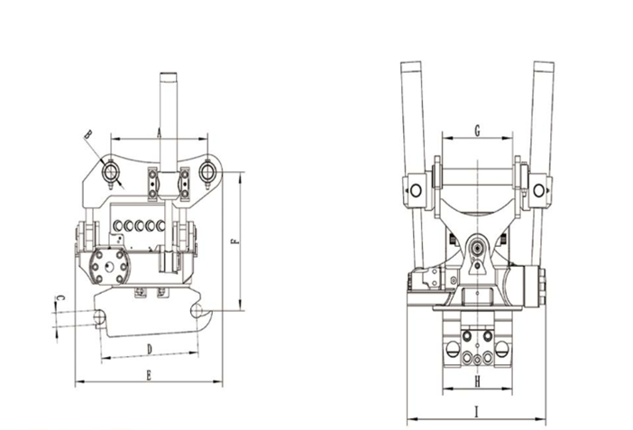
| Width A(mm) | 300 | 430 | 480 | 600 | 670 | |
| Width B(mm) | 40 | 50 | 60 | 70 | 80 | |
| Width C(mm) | 40 | 50 | 60 | 70 | 80 | |
| Width D(mm) | 300 | 430 | 480 | 600 | 670 | |
| Width E(mm) | 488 | 657 | 807 | 939 | 950 | |
| Width F(mm) | 418 | 504 | 664 | 634 | 680 | |
| Width G(mm) | 200 | 270 | 340 | 450 | 590 | |
| Width H(mm) | 198 | 268 | 338 | 448 | 588 | |
| Width I(mm) | 433 | 533 | 589 | 645 | 650 | |
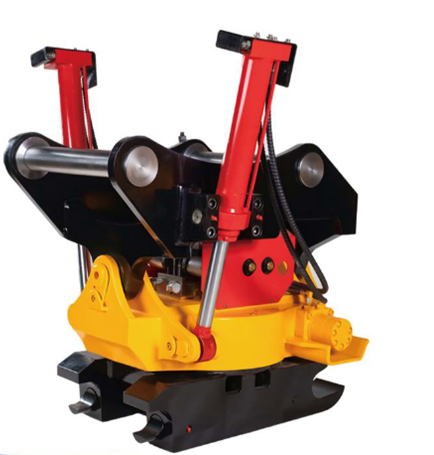
SCEW-SWING TYPE TILTROTATOR
| SCEW-SWING TYPE TILTROTATOR | |||||
| Model | GTR-30B | GTR-40B | GTR-50B | GTR-60B | |
| Applicable Excavator(T) | 1.5-3.0 | 3.0-7.0 | 7.0-12.0 | 12.0-16.0 | |
| Pin Dia(mm) | 30 | 40 | 50 | 60 | |
| Working Pressure(Mpa) | 18.0-21.0 | ||||
| Working Flow(L/min) | 20.0-35.0 | 30.0-80.0 | 30.0-80.0 | 40.0-120.0 | |
| Max. Circuit Pressure(Mpa) | 2.5 | ||||
| Quick Coupler Connector Dia | G1/4 | G1/4 | G1/2 | G1/2 | |
| Weight(kg) | 126 | 188 | 305 | 508 | |
| Rotation | Output Torque(N.m) | 700 | 3500 | 8000 | 9500 |
| Axial Load(kN) | 14.4 | 63 | 136 | 190 | |
| Radial Load(Kn) | 11.1 | 48 | 115 | 148 | |
| Angle(°) | ±360 | ||||
| Time(s) | 7 | ||||
| Flow Rate(L/min) | 24 | 25 | 50 | 60 | |
| Tilt | Swing Torque(N.m) | 900 | 3200 | 7000 | 9000 |
| Angle(°) | ±90 | ||||
| Time(s) | 5 | ||||
| Flow Rate(L/min) | 7 | 7.5 | 19 | 21 | |
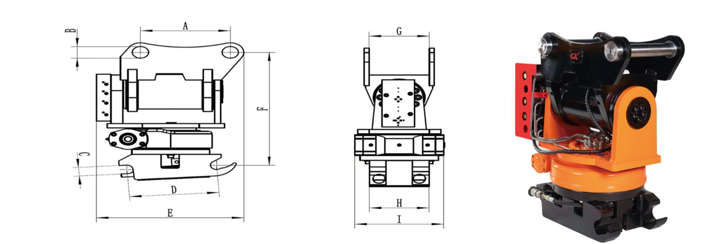
| Width A(mm) | 230 | 300 | 430 | 480 | |
| Width B(mm) | 30 | 40 | 50 | 60 | |
| Width C(mm) | 30 | 40 | 50 | 60 | |
| Width D(mm) | 230 | 300 | 430 | 480 | |
| Width E(mm) | 375 | 492 | 603 | 717 | |
| Width F(mm) | 480 | 530 | 642 | 729 | |
| Width G(mm) | 180 | 200 | 270 | 340 | |
| Width H(mm) | 178 | 198 | 268 | 338 | |
| Width I(mm) | 210 | 295 | 360 | 445 | |
S Standard Data
| SIZE | Width
(mm) |
Shaft C-C
(mm) |
Shaft Dia
(mm) |
Positive Torque(kNm) | Negative Torque(kNm) | Machine Weight(T) |
| S30/150 | 150 | 200 | 30 | 28 | 20 | 2 |
| S30/180 | 180 | 230 | 30 | 28 | 20 | 2 |
| S40 | 200 | 300 | 40 | 35 | 23 | 6 |
| S40/240 | 240 | 300 | 40 | 40 | 26 | 7 |
| S45 | 290 | 430 | 45 | 65 | 42 | 11 |
| S50 | 270 | 430 | 50 | 65 | 42 | 11 |
| S60 | 340 | 480 | 60 | 150 | 75 | 18 |
| S70 | 450 | 600 | 70 | 300 | 195 | 30 |
| S80 | 590 | 670 | 80 | 600 | 390 | 40 |
| S90/620 | 620 | 750 | 90 | 1000 | 650 | 70 |
| S90/750 | 750 | 750 | 90 | 1000 | 650 | 70 |
| S100 | 750 | 900 | 100 | 1200 | 775 | 85 |
| S120 | 925 | 870 | 120 | 1600 | 1000 | 100 |
GTR Series Grapple Technical Data
| Model | GTRG-40 | GTRG-50 | GTRG-60 | GTRG-70 |
| Weight | 40 | 46 | 75 | 110 |
| Max Lifting Capacity | 350 | 500 | 900 | 1200 |
| Recommend Machine | GTR40 | GTR50 | GTR60 | GTR70 |
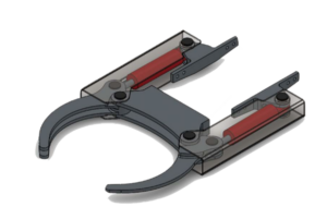
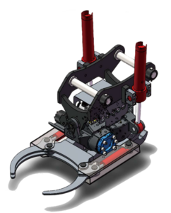
Measurement Specification
| Model | GTRG-40 | GTRG-50 | GTRG-60 | GTRG-70 |
| A | 425 | 520 | 825 | 960 |
| B | 356 | 430 | 490 | 560 |
| C | 486 | 570 | 664 | 736 |
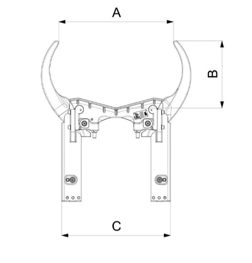
Control System
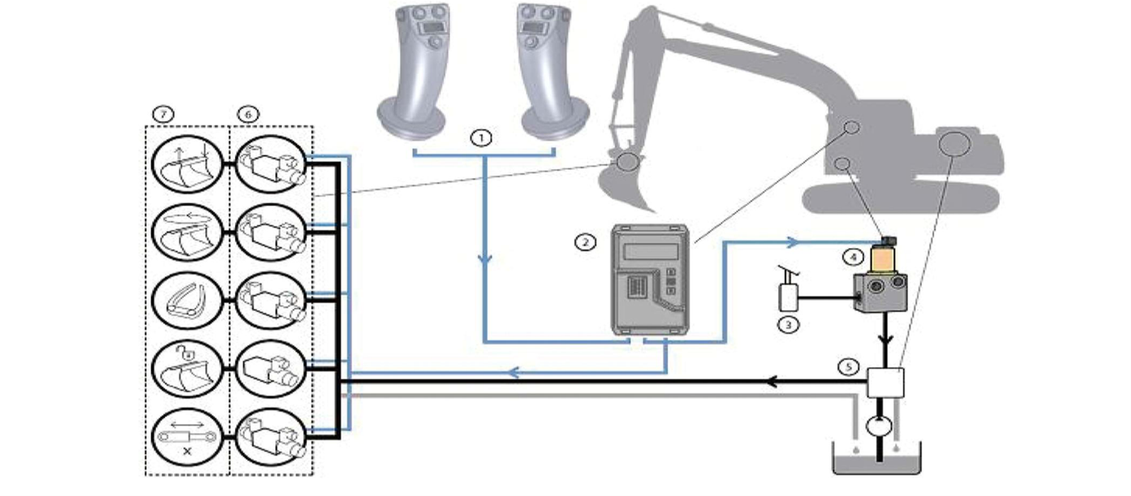
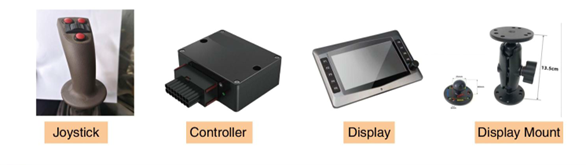
The controller system consists of a controller, display, joystick, solenoid valve group, wiring harness and other components.
Connection and commissioning of hydraulic and control systems
- Hydraulic System:
- Connect the inlet and outlet oil pipes of the hydraulic wrist to the spare hydraulic lines on the main machine.
- Control System:
- Connect the controller to the wiring harness inside the cab via connectors.
- Replace the original excavator handle with the left and right control handles(multi-function handles with proportional control) supplied with the wrist.
- Connect the control handles to the controller according to the operating instructions and fix the controller display in a suitable position in the cab.
- Adjust the parameters of the controller to regulate the performic of the hydraulic wrist.
- Send commands to the controller through the left and right handles. The left and right handles can respectively realize compound actions such as left and right rotation, tilting, and quick change.
Automatic hydraulic coupling
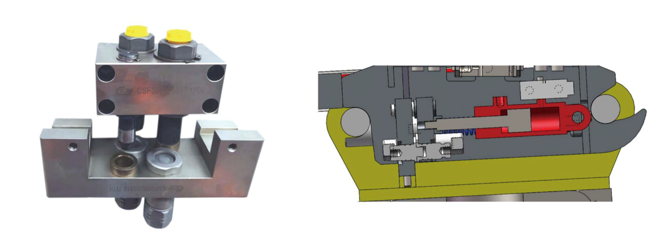
The Tiltrotator offers an automatic hydraulic connection feather, streamlining tool changes and boosting efficiency.
Safety system
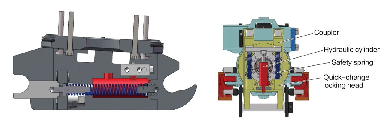
The quick change device at the lower end of all Tiltroator is equipped with a reliable safety interlock to prevent accidental detachment of attachments during operation, significantly enhancing operational safety